If you’ve ever tried to build a microprocessor from scratch, you know it’s a battlefield full of hazards, memory control, and instruction handling. A true digital mess. In the middle of that chaos, I came across a tool that completely changed the way I see FPGA development: LiteX.
What is LiteX?
LiteX is a framework for designing SoCs (System on Chip) on FPGA, transforming the process into something like assembling LEGO blocks: you pick a processor, add controllers, memory, peripherals, and done! Everything fits together elegantly and cleanly. Most impressive of all: integrating a RISC-V processor takes only minutes—literally. In a traditional setup, this could take weeks or even months.
Installing LiteX
To get started, you’ll need a Linux environment (it works on Windows too, but let’s be honest—Linux is smoother). You’ll also need Python and synthesis tools for your FPGA. If you’re using a Tang Nano 9K, you can take advantage of Apicula, an open-source tool for this family of FPGAs.
Installation Steps
Installation is straightforward: clone the repository and run the installer:
wget https://raw.githubusercontent.com/enjoy-digital/litex/master/litex_setup.py
chmod +x litex_setup.py
./litex_setup.py --init --install --user --config=standard
With that, you’re ready to start building your SoC. LiteX handles all dependencies for you, so you don’t have to worry about missing packages or conflicts. If you run into issues, I recommend checking the official LiteX repository documentation.
My First SoC: Blink and UART on Tang Nano 9K
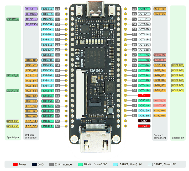
With LiteX installed, it’s time to build our first SoC. For this example, we’ll use the Tang Nano 9K, a small but powerful FPGA. Inside the litex-boards directory, there are two key types of files:
- Platform: Defines the physical pins and peripherals of the FPGA.
- Target: Defines the SoC itself—i.e., the modules and peripherals to be integrated.
To build the SoC, create a file called tangnano9k.py in the targets directory and run:
python3 tangnano9k.py --build
This generates the bitstream and configuration files in the build/ folder. To load it onto the FPGA:
python3 tangnano9k.py --load
And that’s it! The user LED should start blinking.
It also enables a UART console at /dev/ttyUSB0 at 115200 baud:
litex_term /dev/ttyUSB0 --speed 115200
Adding a GPIO Peripheral
So far, so good—but a SoC without useful peripherals is like a car without wheels. Let’s integrate a GPIO into our design.
The two key files are:
platform.py: Defines the physical FPGA pins.target.py: Defines the SoC and its peripherals.
Defining GPIO in platform.py
("gpio_tristate", 0,
    Pins("25 26 27 28 29 30 33 34"),
    IOStandard("LVCMOS33")
),
In this case, we’re defining an 8-bit GPIO connected to pins 25 to 34 of the FPGA. You can change the pins according to your design.
Here, there’s a distinction between logical and physical pins: physical pin 25 is logical pin 0, 26 is 1, and so on.
Instantiating GPIO in target.py
self.gpio = GPIOTristate(platform.request("gpio_tristate"))
self.add_csr("gpio")
Here we instantiate the GPIO and add it to the SoC. GPIOTristate is a class that handles the input/output logic. The add_csr function adds the GPIO to the SoC’s register space, enabling C code to access it.
Controlling GPIO from C
With the GPIO added, it’s time to control it using C. LiteX provides a set of functions to access the GPIO registers. Here’s how:
GPIO Access Functions
/* GPIO Access Functions */
static inline uint32_t gpio_oe_read(void) {
	return csr_read_simple((CSR_BASE + 0x0L));
}

static inline void gpio_oe_write(uint32_t v) {
	csr_write_simple(v, (CSR_BASE + 0x0L));
}

static inline uint32_t gpio_in_read(void) {
	return csr_read_simple((CSR_BASE + 0x4L));
}

static inline uint32_t gpio_out_read(void) {
	return csr_read_simple((CSR_BASE + 0x8L));
}

static inline void gpio_out_write(uint32_t v) {
	csr_write_simple(v, (CSR_BASE + 0x8L));
}
C Usage Example
Here’s an example of how to activate a bit on the GPIO. The function set_gpio_bit takes a bit number (0–31) and activates it in the GPIO output register using the access functions shown above.
void set_gpio_bit(uint8_t bit) {
    if (bit > 31) {
        printf("Error: Bit must be between 0 and 31.\n");
        return;
    }

    uint32_t oe_value = gpio_oe_read();
    oe_value |= (1 << bit);   // Set bit in OE register
    gpio_oe_write(oe_value);

    uint32_t out_value = gpio_out_read();
    out_value |= (1 << bit);  // Set bit in output register
    gpio_out_write(out_value);

    printf("Bit %d activated. Current GPIO_OUT value: 0x%08X\n", bit, gpio_out_read());
}
With this and other demo functions I’ve created in the tutorial repo, you can control GPIOs from your C code. You can find the complete code in my GitHub repository.
In this example, there are functions like blink to make a GPIO pin blink an LED, and a few others to read pin states.
Conclusion
LiteX revolutionizes how we design SoCs on FPGAs, letting us assemble peripherals and processors like LEGO pieces. With just a few lines of code and the power of LiteX, we can control GPIOs, UARTs, and even run C code on a RISC-V core we built ourselves.
Ready to build a SoC with more peripherals and explore beyond the basic examples? 🚀